RC-5 version: 2012/07/15
NEC version: 2015/03/18
designed by Peter JAKAB
Control anything with your remote control. This receiver works with RC-5 and NEC format IR remote controls, depending on the firmware used. The receiver has 11 output channels, and each channel can have up to 4 buttons (on, off, toggle, momentary-on) associated with it.
The output types are:
The firmware for the receiver already
contains a default button layout ready to test operation, so you can
skip this section for the first time. The default button associations for the RC-5 version are:
| channel |
toggle |
off |
on |
momentary-on |
| #0 |
0 |
|||
| #1 |
1 |
|||
| #2 |
2 |
|||
| #3 |
3 |
|||
| #4 |
4 |
|||
| #5 |
5 |
|||
| #6 |
6 |
|||
| #7 |
7 |
|||
| #8 |
8 |
|||
| #9 |
9 |
|||
| #10 |
VOL - |
VOL + |
To enter programming mode, setup the switches as this: B0:ON, B1, B2, B3: OFF then turn on the circuit.
To erase all button associations, setup the switches as this: B0, B1, B2, B3: ON then turn on and off the circuit.
| operation |
B0 |
B1 |
B2 |
B3 |
| enter programming mode at power-on |
ON |
OFF |
OFF |
OFF |
| erase all button associations at power-on |
ON |
ON |
ON |
ON |
After entering the programming mode, switches B1-B3 select the operating mode of the remote control button being learnt.
| operation |
B1 |
B2 |
B3 |
| clear the next button pressed from memory |
ON |
OFF |
ON |
| the next button pressed turns the selected output channel OFF |
OFF |
OFF |
ON |
| the next button pressed turns the selected output channel ON |
OFF |
ON |
OFF |
| the next button pressed toggles the selected output channel |
OFF |
ON |
ON |
| the next button pressed turns the selected output channel ON for the time being pressed |
ON |
OFF |
OFF |
Setup the switches B1-B3 according to the desired output type, then select the associated output channel with switches B4-B7.
| channel |
B4 |
B5 |
B6 |
B7 |
| #0 |
OFF |
OFF |
OFF |
OFF |
| #1 |
ON |
OFF |
OFF |
OFF |
| #2 |
OFF |
ON |
OFF |
OFF |
| #3 |
ON |
ON |
OFF |
OFF |
| #4 |
OFF |
OFF |
ON |
OFF |
| #5 |
ON |
OFF |
ON |
OFF |
| #6 |
OFF |
ON |
ON |
OFF |
| #7 |
ON |
ON |
ON |
OFF |
| #8 |
OFF |
OFF |
OFF |
ON |
| #9 |
ON |
OFF |
OFF |
ON |
| #10 |
OFF |
ON |
OFF |
ON |
When you have finished programming, setup B0-B7 all OFF, and turn off the circuit.
An example programming session:
| channel |
toggle |
off |
on |
momentary |
| #0 |
0 |
|||
| #1 |
1 |
|||
| #2 |
||||
| #3 |
||||
| #4 |
||||
| #5 |
5 |
|||
| #6 |
6 |
|||
| #7 |
||||
| #8 |
||||
| #9 |
||||
| #10 |
VOL - |
VOL + |
The B0-B7 switches must all be turned OFF to enter normal decoding operation. In this mode, any remote control button learnt will light up the VALID_LED for the duration the button is pressed. Output channel states will change according to the type setup learnt.
Connect the circuit to a 12VDC, min.
500mA output power supply. Output should be able to supply enough
current when all the relays are turned on. Relay coils are 12VDC.
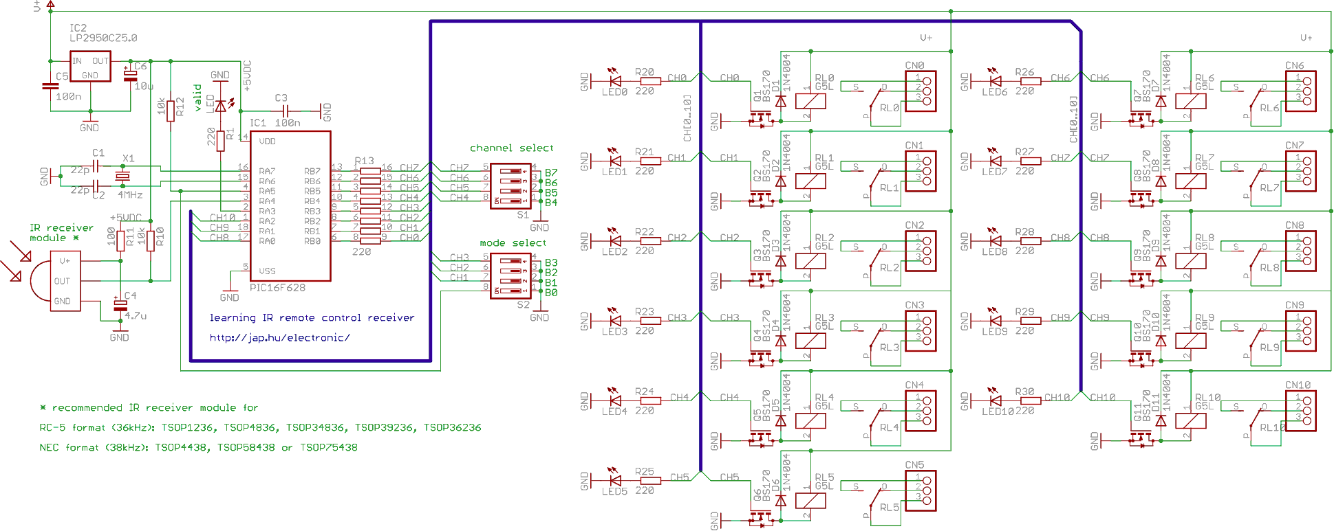
| part |
count |
description |
| IC1 | 1 |
PIC16F627 or PIC16F627A or PIC16F628 or PIC16F628A - Microchip microcontroller, programmed |
| IC2 |
1 |
LP2950CZ5.0 - voltage regulator, 5VDC output |
| IC3 |
1 |
IR receiver module, recommended part numbers:
|
| C1, C2 |
2 |
22pF ceramic capacitor |
| C3, C5 |
2 |
100nF ceramic capacitor |
| C4 |
1 |
4.7uF/6.3V electrolytic capacitor |
| C6 |
1 |
10uF/16V electrolytic capacitor |
| R1, R13x8, R20-R30 |
20 |
220 ohm resistor (1/8 W) |
| R10, R12 |
2 |
10k resistor (1/8 W) |
| R11 |
1 |
100 ohm resistor (1/8 W) |
| D1-D11 |
11 |
1N4004 diode |
| LED |
1 |
3 mm LED, any color |
| LED0-LED10 |
11 |
3 mm LED, any color |
| Q1-Q11 |
11 |
BS170, BSS138, 2N7002 or similar N-channel MOSFET transistor |
| RL0-RL10 |
11 |
G5LE 12V relay |
| S1, S2 |
2 |
DIL4 piano switch |
| X1 |
1 |
HC49 4MHz crystal |